Nikon’s Roots / Vol. 19
AE on flagship cameras
The 1970s was the era when TTL-AE was becoming more common in SLR cameras. Advances in electronics made it possible to use semiconductor ICs in cameras, and advanced signal processing made it possible to electronically control shutter speed and aperture. However, this cutting-edge technology was mainly incorporated into mid-range cameras, and it took quite some time for it to be applied to top-of-the-line flagship cameras.
Professional photographers, such as those in the press, who use the highest quality cameras, are conservative and place the utmost importance on reliability. They absolutely cannot afford to have a problem that prevents them from taking a photo when it really counts. Therefore, manufacturers who develop cameras are all the more cautious and do not release them to the public until they are absolutely confident in the product.
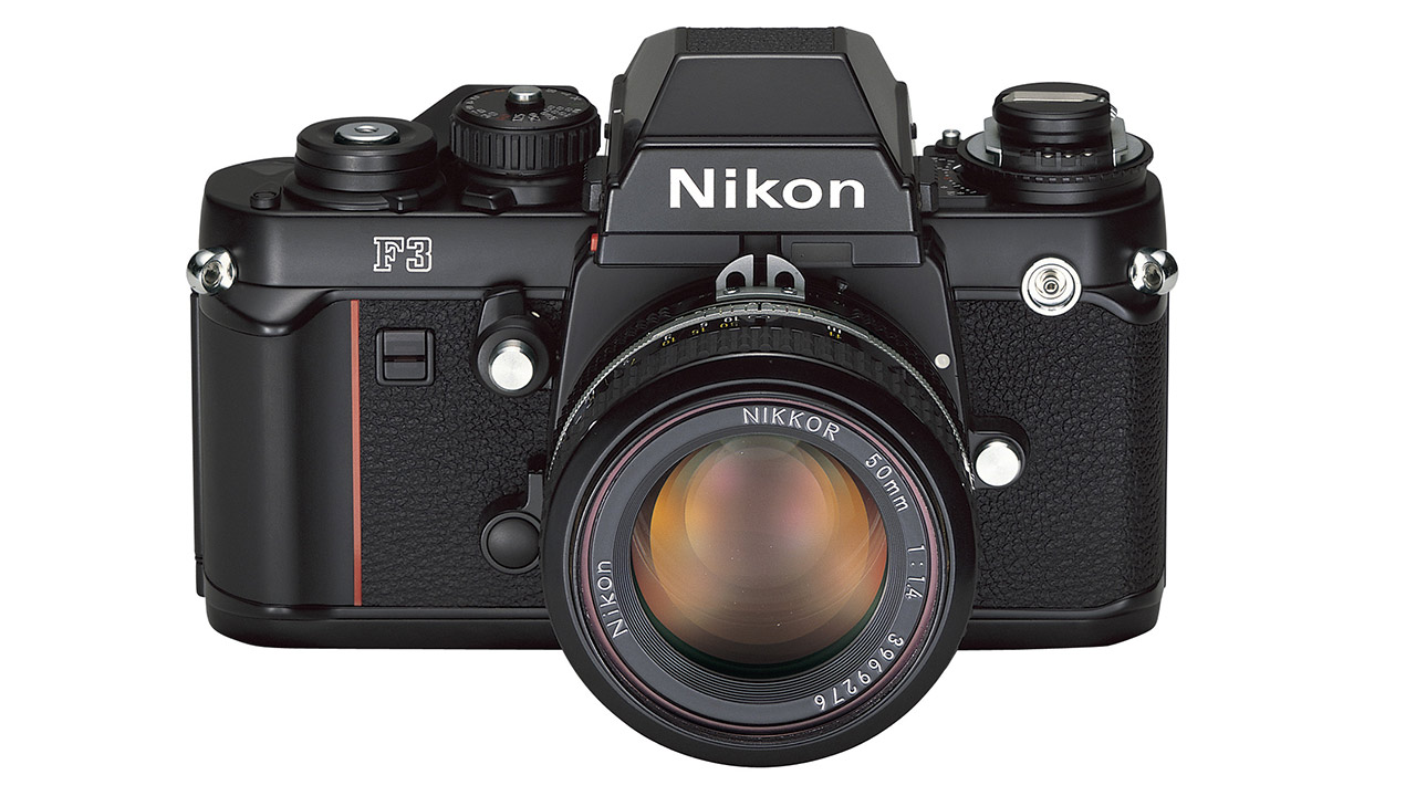
Nikon F2 was a Photomic design, but this changed for the F3.
When releasing a successor to the Nikon F2, Nikon decided from the start that it would use TTL-AE, but the initial plan was to continue the Photomic format that had been used in the Nikon F and F2. The body would house the electronic shutter and circuitry for manual control, while the viewfinder would house the TTL metering light-receiving element and the circuitry that processes the photocurrent to automatically control the shutter speed.
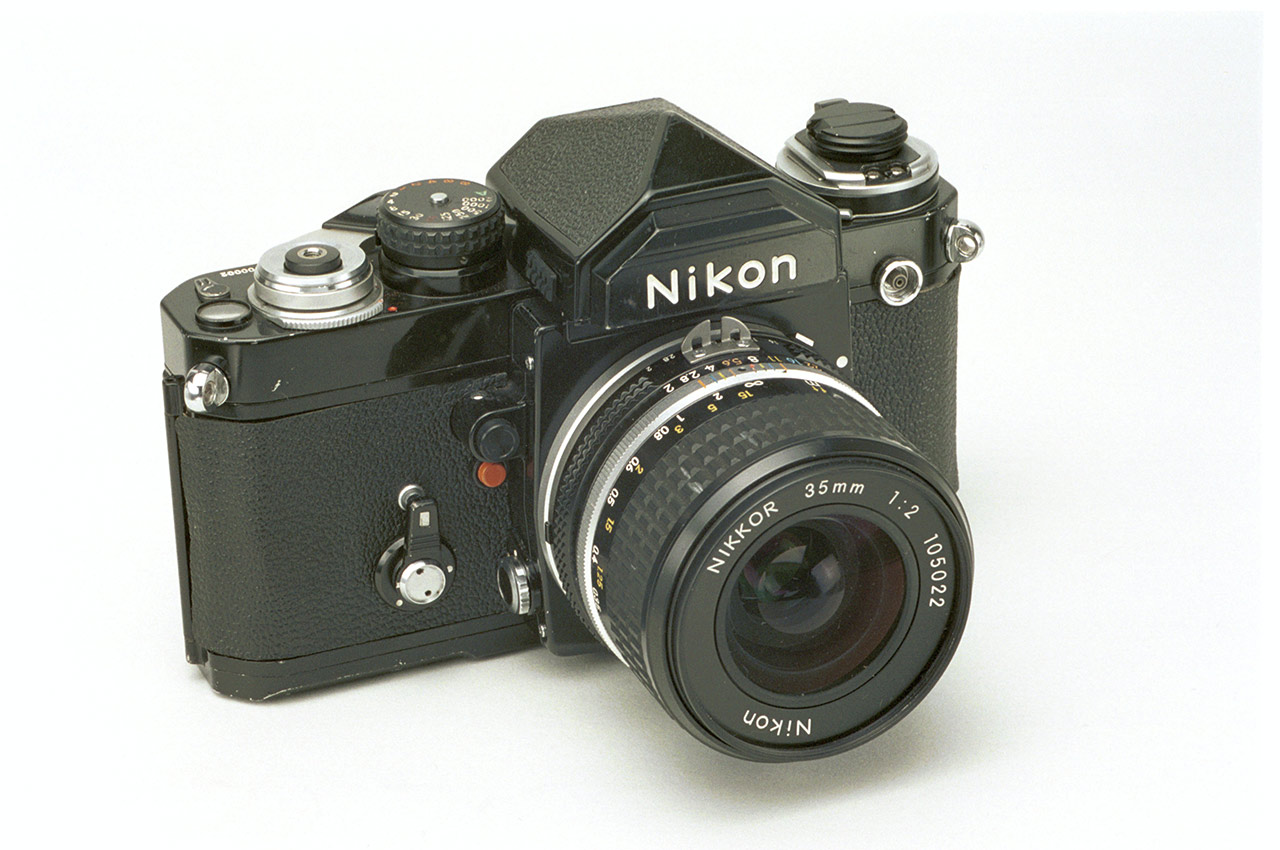
Models with viewfinders other than the Photomic would only be able to use manual shutter speeds, but attaching a Photomic viewfinder would enable aperture-priority AE. Essentially, this was the same format as the Minolta X-1.
However, the Photomic format inevitably required a large viewfinder, and there were issues with AE becoming unusable when switching to a high-magnification viewfinder or other option. Therefore, the Photomic format was abandoned in subsequent prototypes.
However, this did not mean that the Photomic format was discontinued, as it was later revived in the Nikon F4.

Body metering – new for the Nikon F3
Until then, Nikon had placed the light-receiving element for TTL metering on the exit surface of the viewfinder pentaprism, or next to or above the eyepiece. However, this became unusable, so they developed a new system called “body metering” that places the light-receiving element on the body.
After much consideration, they decided to place the light-receiving element at the bottom of the mirror box, and use a sub-mirror to guide subject light that passes through the main mirror to this light-receiving element. This is the same optical system that was used in later AF SLRs to direct light to the AF sensor. However, while the center of the main mirror is usually a half-mirror to split the subject light, the Nikon F3 does not use a half-mirror, but instead uses a pinhole mirror with many extremely tiny holes, each measuring 20 x 30 microns, on its reflective surface.
This was done to prevent exposure errors when using a polarizing filter (PL filter) because the reflected and transmitted light from a half mirror are both polarized. This problem could be solved by using a circular polarizing filter (C-PL filter), but circular polarizing filters were not yet widely used at the time.
Since this pinhole mirror is only in the center of the main mirror, the metering sensitivity distribution is more center-weighted than other Nikon cameras.
Furthermore, when the mirror is raised during shooting, the light-receiving element located on the bottom of the body receives reflected light from the film surface, and also functions as a sensor for TTL flash control of the strobe.
Body Metering System Diagram:

Drum-type focal-plane shutter
The Nikon F3 used a drum-type focal-plane shutter, just like the F2 and earlier models. Nikon’s previous TTL-AE SLR cameras had used square-type electronically controlled shutters from Copal or Seiko, but the square-type focal-plane shutters of the time were not yet reliable enough for flagship cameras. That’s why the proven three-axis drum-type shutter was modified to be electronically controlled and made into a unit shutter. You might think that unit shutters only refer to square shutters, but drum-type shutters also have many advantages, and they have been used in several cameras since the Canon AE-1 in 1976.

Photometry and control circuit
The shutter speed control uses a quartz crystal oscillator. Furthermore, a digital LCD display shows the shutter speed in auto mode. These were quite advanced and challenging choices for a Nikon flagship camera. Although LCD displays have a proven track record in calculators and wristwatches, there were concerns about their reliability. Rumors that they would deteriorate over time and stop displaying information after a few years, regardless of whether they were used or not, were a major concern. If this were true, the LCD panels stored separately as repair parts would also deteriorate over time and become unusable. However, these fears proved unfounded. Most of the LCD displays used in the Nikon F3 still function flawlessly, even today, decades later.
These new functions were added to the metering and control circuits developed for previous models such as the Nikon FE, resulting in an increase in circuit size. A flexible printed circuit (FPC) was used to mount the circuit in the camera, but since the pentaprism part of the viewfinder on the Nikon F3 is removable, the roof of the pentaprism could not be used as circuit space. The circuitry had no choice but to be mounted on a large FPC that ran from the front of the winding side of the camera body, through the bottom of the body, and then through the front of the rewinding side to the LCD panel in front of the viewfinder screen.
Semi-preset resistors
What is noteworthy here are the vertically aligned semi-preset resistors on both sides of the front of the body. These are used to make final adjustments to compensate for variations in circuit elements and variations during assembly. For the Nikon F3, the assembly line was equipped with a computer-controlled automatic adjustment device that used a motor to turn these semi-preset resistors while monitoring the output signals from the circuits in each body, thereby making final adjustments. For this reason, adjustment holes were provided in the die-cast front panel.

Girogetto Giugiaro Design
The Nikon F3 design came from the mind of Giorgetto Giugiaro, famous for his car designs. I heard that he first approached them about designing a camera.
The red line on the front of the body and the slanted silhouette of the MD-4 motor drive system show a style that had never been seen before in Nikon cameras. In fact, Giugiaro also had a hand in the Nikon EM, which was released around the same time. Giugiaro went on to work on many Nikon cameras after that.
Variations
There are many variations of the Nikon F3. First, in 1982, the Nikon F3 High Eyepoint was released. The eyepiece eyepoint was enlarged to 25mm so that the entire field of view could be seen easily even when wearing glasses, but in return, the viewfinder magnification was slightly reduced and the eyepiece thread diameter was larger. This high eyepoint viewfinder became the standard specification for subsequent Nikon SLR cameras.
Using titanium for the exterior of a camera body had been attempted since the days of the Nikon F2, and the Nikon F3 also released a model called the F3/T. Initially it was titanium-colored, but later a black model was also released.
The Nikon F3P was also developed for professionals such as journalists, with several changes including the addition of a hot shoe and improved waterproofing. This model was later sold to the general public under the name Nikon F3 Limited. Other variations of the Nikon F3 include the Nikon F3H, which featured a faster motor drive frame rate, and two cameras specially developed for NASA.

Originally written in Japanese by Toyoda Kenji | Profile
Mr. Toyota was born in Tokyo in 1947. He worked for Nikon Corporation for more than 30 years, designing single-lens reflex cameras and working in electronic imaging. He will then teach as a part-time lecturer at the Department of Photography, College of Art, Nihon University until 2021. Current positions include Fellow and Auditor of the Photographic Society of Japan, Cooperating Committee member of the Japan Opto-Mechatronics Association, and judge of Japan Camera Museum’s “Japanese Historical Cameras.” He has written numerous books, including “Professor Toyoda’s Camera Mechanism Lectures” (Nippon Camera Co.), and “Cousins of the Nikon Family” (Asahi Sonorama).